

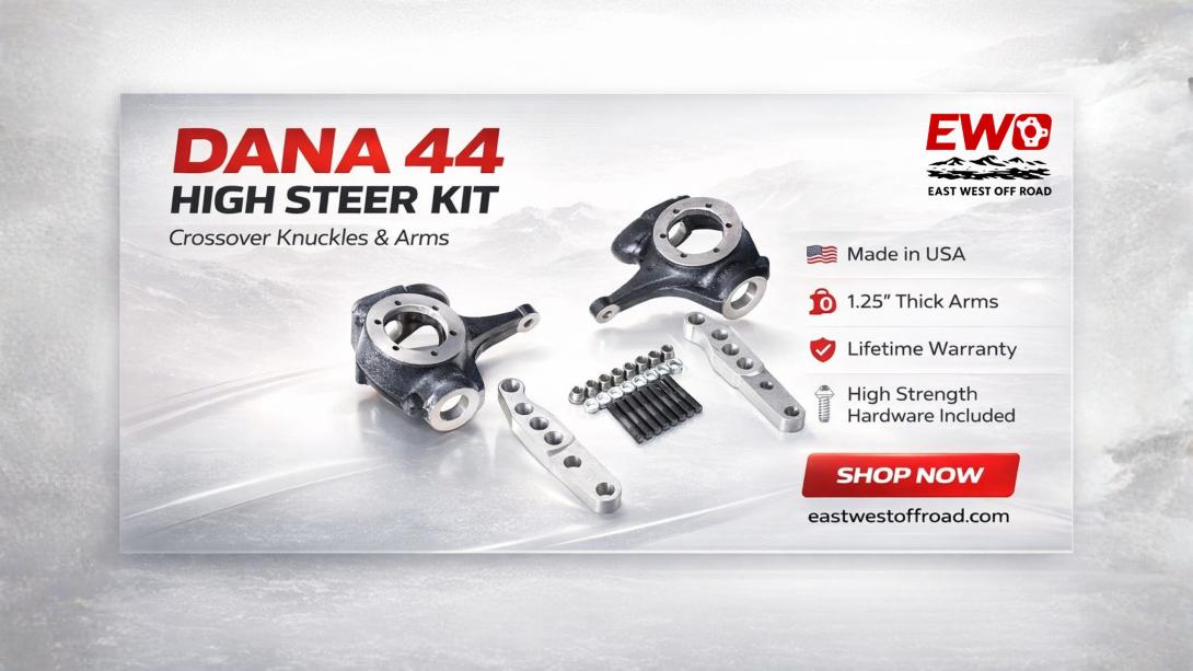
Buy Now: https://www.eastwestoffroad.com/product/dana-44-high-steer-crossover-knuckles-and-arms-kit
A 1 ton steering upgrade Dana 44 linkage compatibility review must follow the steering path joint by joint. Start at the knuckle taper, move through the tie-rod ends and tie rod, identify the passenger-side drag-link attachment, then continue through the drag link and pitman arm to the steering box. A verified interface at one end does not prove compatibility at the next.
For EWO E90178, the known axle-side facts are bottom-down-taper flat-top knuckles, four-hole high-steer arms, and a design intended for 7/8-inch Chevy 3/4-ton tie-rod ends. The tie-rod ends, tubes, adjusters, drag link, pitman arm, and steering box are not listed as included. Each must be selected by exact taper, thread, length, articulation, travel, and clearance—not by “1 ton” terminology alone.
Verify the Knuckle and Tie-Rod Interfaces
Knuckle taper
The EWO knuckles use the manufacturer-specified bottom-down taper. Confirm insertion direction, matching joint taper, seating depth, and clearance before purchasing or machining related parts. A near-match is not an acceptable steering interface.
Tie-rod ends and tube
The intended 7/8-inch Chevy 3/4-ton ends need compatible threads, adjusters or bungs, tube length, and orientation. For a useful inspection, specify right/left-hand threads, adjustment range, jam nuts, and joint-center length as a system. One incorrect thread direction or insufficient adjustment range can invalidate the assembled tie rod.
Specify the Drag Link and Pitman-Arm Connection
Passenger-arm assignment
The four-hole passenger arm must accommodate the intended drag-link and tie-rod arrangement according to current instructions. In practical terms, map hole use, vertical separation, joint bodies, boots, and articulation. The links must not collide through steering or suspension movement.
Drag-link length
Drag-link length and pivot locations influence its arc and the steering response through suspension travel. During planning, measure joint centers at ride height and model compression, droop, and both locks. A convenient off-the-shelf length is not automatically the correct geometric length.
Validate the Complete Moving Chain
Pitman-arm interface
The box-side joint or taper must match the pitman arm, and the pitman-arm position must support the intended arc and travel. For the finished system, confirm steering-box output, pitman-arm swing, drop or position, and joint articulation. Do not assume a knuckle-side tie-rod end will also fit the pitman side.
System travel
The steering box, knuckle stops, joints, tie rod, and drag link must reach useful travel without binding or contact. Before parts are committed, cycle the complete assembly with safe support and observe every interface. Any single component becoming an unintended stop is a failed compatibility check.
End-to-End Compatibility Chain
Require a documented PASS at each link before the next component is ordered.
1. PASS 1: Axle and flat-top knuckles positively identified and compatible.
2. PASS 2: Bottom-down knuckle tapers match the intended 7/8-inch Chevy 3/4-ton ends.
3. PASS 3: Tie-rod threads, bungs/adjusters, jam nuts, tube, and center length are specified.
4. PASS 4: Driver/passenger arm holes and mounting hardware match current instructions.
5. PASS 5: Passenger-side drag-link end, arm location, and joint articulation are verified.
6. PASS 6: Drag-link tube, ends, adjustment, length, and route are specified.
7. PASS 7: Pitman arm and steering-box travel/interface are confirmed.
8. PASS 8: Full steering/suspension travel, clearances, stops, toe, and alignment pass inspection.
Why One Correct Tie-Rod End Is Not Enough
A builder may confirm that a chosen 7/8-inch end seats correctly in the knuckle and then assume the rest of the linkage will follow. The tie-rod tube may use incompatible threads, the passenger-arm hole may not support the intended arrangement, or the pitman arm may require a different joint. End-to-end planning catches those breaks before the vehicle is disassembled. The compatibility chain is complete only when every joint, tube, adjustment range, and motion condition has passed.
Vehicle and Axle Verification
Important: E90178’s stated axle and vehicle applications remain the first gate. Confirm the Chevy Dana 44 or GM 10 Bolt configuration, sides, bottom-down taper, outer components, suspension height, and wheel/brake clearance. Then complete the separate linkage chain. A search for a 1-ton upgrade does not prove that the existing pitman arm, steering box, or tube system is compatible.
Safety-Critical Installation Notes
Important: Custom linkage design, machining, and welding should be handled by qualified professionals when required. Use current instructions for each manufacturer’s component and do not transfer torque or assembly assumptions across products. Inspect taper and hardware seating, jam-nut and adjustment configuration, joint articulation, steering stops, full travel, toe, and alignment before use and during the recommended reinspection.
How the EWO Package Supports the Plan
Use E90178 as the known axle-side portion of the chain only when its flat-top pair, four-hole arms, mounting set, and intended ends match the plan. The package gives clear starting interfaces; it does not remove the need to engineer the tubes and box-side connection. Keep the arm-specific lifetime warranty recorded separately from linkage-component policies.
Convert Assumptions Into Project Records
Turn the article’s end-to-end compatibility chain into a dated project record. For “PASS 1: Axle and flat-top knuckles positively identified and compatible.” retain a clear photograph, measurement, part number, or written manufacturer confirmation. Do the same for “PASS 2: Bottom-down knuckle tapers match the intended 7/8-inch Chevy 3/4-ton ends.” and “PASS 3: Tie-rod threads, bungs/adjusters, jam nuts, tube, and center length are specified..” Mark every unresolved item as open rather than filling it with a likely answer. This record helps the buyer, installer, alignment technician, and future owner understand why the selected parts were considered compatible, and it creates a baseline for investigating any later contact, play, alignment change, or steering behavior.
Before the vehicle returns to service, compare the completed assembly with the original goal: the builder needs to prove compatibility from knuckle taper through tie rod, drag link, pitman arm, and steering box. Confirm that the solution addresses that specific problem without creating a new clearance, articulation, taper, or serviceability issue. A short written acceptance note should identify who inspected the system, which conditions were checked, the alignment result, and when the first reinspection is due. The note is not a substitute for manufacturer instructions; it is a durable record that the project’s own acceptance criteria were reviewed.
For builders who understand the package boundary and are ready to specify the rest of the linkage, the final review should stay centered on this article’s distinct angle: an end-to-end compatibility chain with a separate pass/fail gate for each joint. Use photographs taken from consistent positions, measurements between joint centers, exact part numbers, and written fitment responses so another competent person can reproduce the decision. If a later change is made to tire size, wheel backspacing, suspension height, pitman arm, steering box, brakes, or axle position, reopen the same review rather than assuming the earlier clearance and geometry conclusions still apply.
What to Do Before Ordering
Draw one line from driver knuckle to steering box and label every taper, thread, joint, tube, and adjustment point. Verify the EWO starting interfaces at https://www.eastwestoffroad.com/product/dana-44-high-steer-crossover-kn…